Every multi-driver loudspeaker system needs a crossover filter to supply the correct frequency band to the individual drivers – bass to the woofer, mid to the midrange, and high to the tweeter. In commercial loudspeaker systems, this is usually done by means of a passive crossover filter with large coils, capacitors, and resistors.
However, this is only done for commercial reasons and certainly not because it is the best and most optimal way to do the filtering – it is simply the cheapest way to do it commercially. The best and most optimal way is to apply an active crossover with separate power amplifiers for each driver in the system.
This can be expensive but unbeatable in dynamic response and options to tweak the system and optimize for your listening space.
In this article, we will introduce our approach to accomplishing this with the electronics we designed to get the best out of your setup.
Products used in this project:


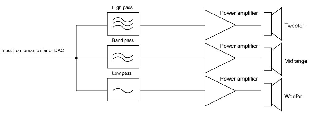
In the schematic on the right, you can find the basic setup for a 3-way active crossover. In the case of a 2-way setup, the bandpass section can be omitted.
Note how the incoming signal is filtered into frequency bands for each driver before amplification. This method of filtering is preferred because the actual slopes of the crossover points are 24dB per octave, in contrast to the 12dB per octave in most passive crossover networks built into commercial speaker systems.
Additionally, the amplitude at the crossover point is at -3dB, which guarantees a flat frequency response at the crossover point with no bump or dip in response where the filter crosses over from one driver to the next.
Please note: never drive the tweeter directly from the power amplifier output. This will destroy it sooner or later. Instead, always add a good quality capacitor in series with it to block DC current. Usually, a 10μF capacitor is used in a 2-way system and a 22μF capacitor in a 3-way system. This capacitor is in the signal path, so investing in a high-quality one is advisable!
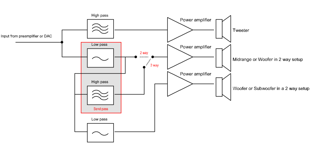
Our implementation differs somewhat from this approach because we wanted to configure the circuit to be used as a three-way, two-way, or two-way filter with subwoofer output.
The input signal is first fed through a high-pass section for the tweeter and a low-pass section that acts as the input of a bandpass section.
In the case of a two-way setup, the output of this low-pass is fed to the woofer amplifier and the input of the low-pass for the subwoofer.
In a three-way setup, the output from the band-pass is fed into the midrange amplifier, and the last low-pass output is used to drive the woofer amplifier.
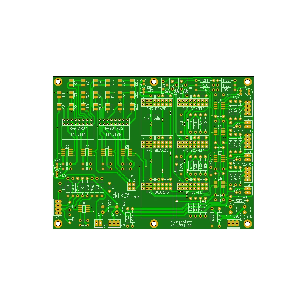
The figure on the right represents the block diagram of an actual filter circuit. The crossover points for the filter stages can be easily set by plugging in two resistor banks that accurately adjust the crossover frequencies. This makes it easy to modify and experiment with the settings to ensure proper driver utilization.
In a three-way setup, there is one for the first high and low-pass, which sets the crossover point between the tweeter and midrange (e.g. 6000Hz), and one for the second stage that sets the crossover point between the midrange and the woofer (e.g. 600Hz).
In a two-way setup, there is one for the first high and low-pass that sets the crossover point between the tweeter and woofer (e.g., 2500Hz) and another for the second stage that sets the cut-off point for the subwoofer (e.g., 150Hz).
In addition, a 0 to -12 dB attenuation circuit is implemented for each output, and balanced and non-balanced outputs are provided to drive the power amplifiers.

Function board headers for each stage are available to add notch filters, delay circuits to correct driver alignment, phase correction, or equalizer circuits.


On the left, you will find a complete stereo filter system setup, including power supplies, transformers, and a system controller. Note that we have designed this as a dual mono system.
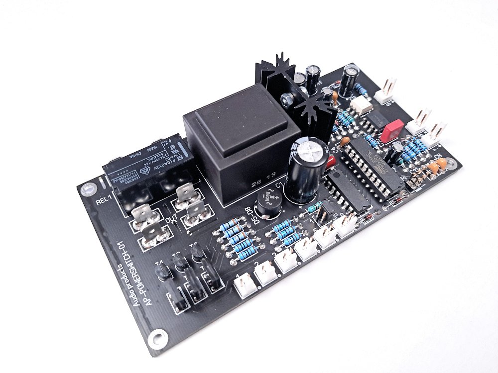
To support the actual filter boards and make it into a usable system, we have designed an additional system controller and power supply.
The system controller handles switching power to the filter system and also controls the power amplifiers by 12V triggering. Three individual 12V trigger lines fire with a one-second interval so they will not be turned on at the same time. This prevents tripping the mains fuse when six amplifiers turn on at the same time.
The system can be turned on/off manually with a single push button but can also be controlled by the pre-amplifier through the 12V trigger input. It also includes an audio detect input to automatically switch on when an audio signal is detected and off again when there is no input for about 15 minutes. This function can be turned on/off with the power button.
The power supply has separate output stages for supplying power to the driver stage and filter stage of the filter board individually. This ensures that the filter stage always has a “clean” supply voltage, regardless of the load on the output stage.
Two large 50VA toroidal transformers complete the setup.
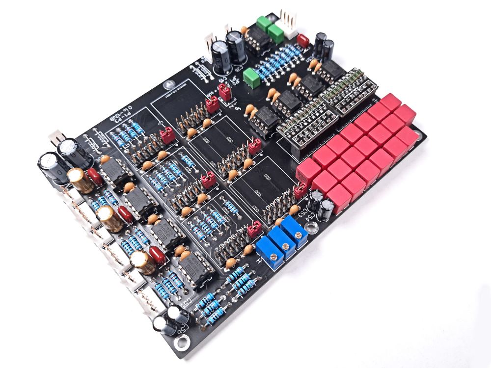
LR24-3B – The crossover filter circuit board.
A completely new PCB has been designed for adopting high end SoundPlus™ Texas Instruments opamps OPA1602 and OPA1612.
The input stage is balanced; however, it can be easily supplied with an unbalanced signal. The outputs are available in both balanced and unbalanced forms, with both options being buffered and having separate output headers.
Additionally, a header is implemented to connect the board to the system controller and provide audio detection for the system.
The board has two separate power supply inputs to supply power individually to the driver stage and filter stage of the filter board. This ensures that the filter stage always has a “clean” supply voltage, regardless of the demand on the output stage.
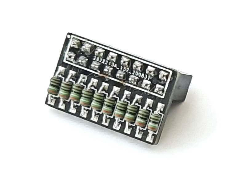
For setting the crossover points on the filter, two pluggable resistor banks have been implemented. One bank sets the crossover point for the high to mid section, while the other sets the crossover point for the mid to low section.
In a two-way system with a subwoofer, the aforementioned mid to low resistor board determines the subwoofer cutoff point.
Two resistor bank plug-in boards are inserted to determine the crossover points of the filter. This way, it is very easy to change the required crossover points. Obviously, these are sold separately from the filter board.
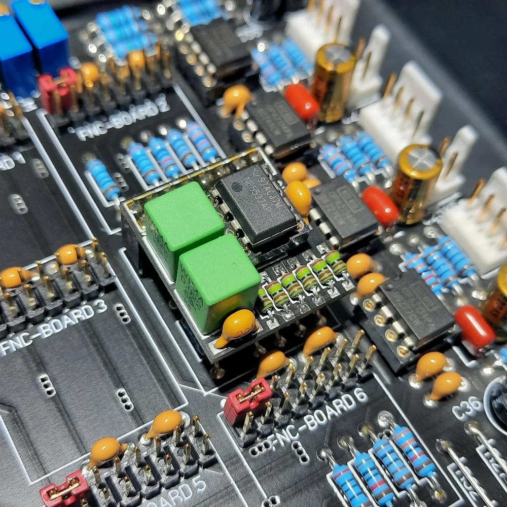
Plugin function boards for Audio products active crossover modules.
Two first order allpass filter sections to correct phase shift between drivers or use multiple sections to correct for offset between drivers (forward placed tweeter).
Dual circuit on the PCB with option to use one or two circuits in series, each stage delays 128 μS.
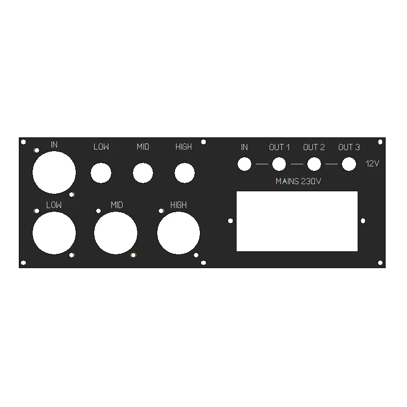
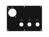
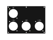
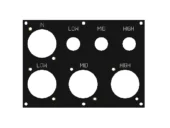
Alternatively, three types of connector panels for input and outputs are available for you to choose from, based on your needs. All of them come with mounted connectors and wiring.
The first bracket has a balanced XLR input and unbalanced RCA outputs.
The third bracket has a balanced XLR input, balanced XLR outputs and unbalanced RCA outputs.
The balanced XLR input can easily be used as an unbalanced input by connecting the “core” of the cable to the “HOT” pin 2 and the shield to the ground pin 1 of the XLR connector. In this case, pin 3 can be ignored.
Also an alternative panel for the power controller is available with mains in and 12V trigger in and output connectors.

PSP05 – Power supply.
This power supply is specially designed for use with the crossover board. Four outputs are available to supply power to two filter boards. Connectors 1 and 3 should be connected to the first board while connectors 2 and 4 are to be connected to the second board.
System control stage.