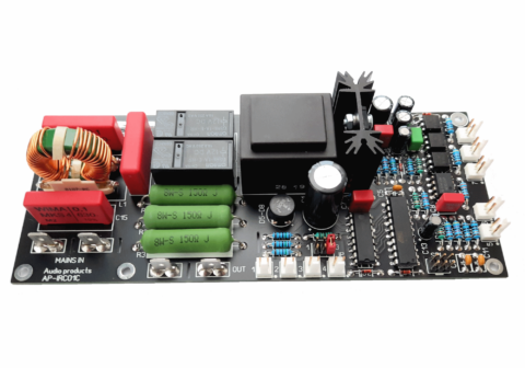
IRC01B and IRC01C are Microcontroller based power supply controllers with inrush current limiter for power amplifiers, the IRC01C in addition to IRC01B has an 1500VA EMI suppression mains filter.
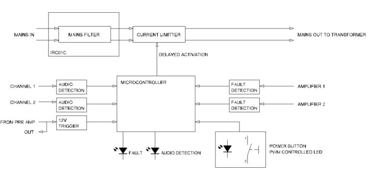
Larger transformers from 500VA and up must not be connected to the mains supply voltage without any form of inrush current restricting circuit. A single transformer should not really be a huge problem however when you have multiple ones like with dual, quadruple or more mono-blocks that are switched on simultaneously this can result in tripping the fusebox main fuse. Keep in mind that next to the transformers also the main power capacitors in the power supply, usually large ones in power amplifiers, have to be charged and this also takes a high peak current. To avoid this a circuit like IRC01 is necessary that will limit current flow at power supply startup for a short while. We have designed the IRC01 to keep track of this and we also added additional functionality to the circuit to make it a real power supply controller.
Powering ON
Power ON the unit can be done in three different ways. First of all with a power button, second by supplying a 12V AC or DC voltage to the 12V trigger input and third by applying an audio signal to one of the audio detect inputs of the module. The power LED output is PWM controlled and when the unit is in the OFF state the power LED will be dimmed to about 10% intensity, when the power is switched on then LED will be slowly brought to full illumination and the unit is then ON.
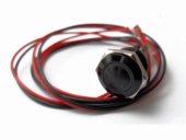
For powering ON the unit with a button a push button with LED illumination can be used or a button with a separate LED. Many fancy illuminated buttons are available on the marked and only your budged is the limit when selecting one however make sure that it is a 1.5-3V or a 12V type. In our shop you can find some models with different LED colors that already have wires and connectors to easily plug in to the unit.

For powering ON the unit with a 12V trigger signal a small PCB with two 3.5mm jack’s and connecting cable is available in our shop. One of the jack’s is for input of the signal and the second jack is signal thru output to connect to the power supply controller in the next power amplifier. A standard 3.5mm mono jack cable can be used as interconnect.

Mains input
The mains input must be connected to the mains voltage through an IEC connector that includes a double pole switch with fuse like
BVA01/Z000/10 in the shop. Use the double poled switch to cut off power to the unit completely.
Mains output
Note that the mains output is always LIVE when the mains input is connected to the mains voltage even when the unit is switched
OFF. In this way a low voltage is always maintained in the power caps of the connected power supply to reduce inrush current and
stress to the power caps when switching ON.
When the unit is switched ON power on the mains output will be reduced for 2 seconds to stabilize the power transformer and
reduce inrush current.
Audio detect
Audio detect can be switched on and off by pushing the power button more than 2 seconds, one blink the audio detect is turned ON
and the LED on Header 2 is ON, two blinks and the audio detect on turned OFF and the LED on Header 2 is OFF. Power must be
switched ON to do this setting (power button pushed and power LED on header 3 is ON).
When audio detect is ON and the unit finds audio on one of the audio inputs header 5 or 6 the unit will switch ON. When no audio is
detected for 15 minutes the unit will go OFF again. The input threshold is about 20mV. If the power to the unit is switched OFF
manually the audio detect function will be disabled temporarily until the unit is switched ON manually again. 12V trigger signals
override the audio detect function.
12V trigger
The 12V trigger input header 7 accepts AC and DC pulsed input (less than 2 seconds), pulse ON pulse OFF, and continuous voltage,
voltage power ON and no voltage power OFF. The unit automatically detects the type of signal applied to the input. The 12V trigger
output header 8 is a loop through from header 7. Do NOT apply a voltage higher than 15V AC/DC to the input.
Amplifier error in
Amplifier error in 1 and 2 accept current source signals up to 30mA to signal amplifier error status.
To signal that an amplifier is connected to the input a voltage must be applied to the input shortly and this way the unit knows an
error circuit is connected. When the input goes high again the unit will enter the error status and switch OFF and rapidly blink the
power LED for a couple of seconds and the LED on header 1 goes ON. The unit can be turned ON manually after this.
Power LED
The power LED is PWM controlled and is never turned off completely rather dimmed to a low level to indicate that power is supplied
to the unit. When the power button is pressed to power ON the unit the power LED will slowly be illuminated to full ON.
Output voltage can be selected by a jumper on the unit to select direct 12VDC or with series 1K5 resistor, with jumper 12V and no jumper 1,3 to 3V.
Power button
The power button must be a momentary push button and only a small signal is switched.
Many types of LED illuminated push buttons are available.
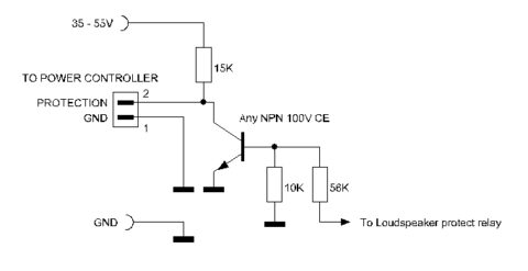
Audio products amplifiers have build in interface for error detection to the IRC01 however if you need to interface to an existing amplifier use the schematic below.
Connections to the board
IN Mains input from IEC terminal with main ON/OFF switch and fuse
OUT Mains output to transformer
Header 1 Error LED
Header 2 Audio detect ON/OFF LED
Header 3 Power LED
Header 4 Power button (push)
Header 5 Audio in 1
Header 6 Audio in 2
Header 7 12V trigger
Header 8 Amplifier error in 1
Header 9 Amplifier error in 2
Example interface circuit for amplifier to error input:
When the amplifier powers UP the relay will be turned OFF and a signal ‘high’ will be applied to the controller input and the
controller knows it has to monitor the input for ‘error’. When the amplifier is stable the relay will be turned on and a signal ‘low’ will
be applied to the controller input. If an error situation occurs the relay will be turned OFF again and a signal ‘high’ on the error input
of the controller will signal the error state of the amplifier to the controller.
Specifications:
Mains input voltage 220 to 240VAC
Max transformer power 1000VA
Power consumption in standby 1W
Max input voltage 12V trigger 15V AC/DC
Max input voltage Amplifier error 5V DC or 30mA
Input sensitivity Audio detect 20mV 5Hz – 20KHz
LED drive on header 1 to 3 12V with jumper or 1K5 series without jumper
Module developed and produced by Audio products


